Hello N64
The Nintendo 64 was my first "real" game console. Chronologically speaking, that title should belong to my humble black-cased, gray-buttoned Game Boy Pocket. But to a dumb kid in the mid-nineties who had not yet discovered Pokémon Red (and thought the Sony PlayStation looked like a "boring gray rectangle"), the Nintendo 64 was the real deal.
Looking back, I still have a lot of fondness for those awkward early years of 3D games. Since that time I've developed some idea of how a computer works at all. So why not try making one of these games? How does one produce a program and run it on the hardware of a Nintendo 64?
I dunno. Let's see.
Skirting Development Dependencies
There are some questions that we need to answer before we can get started.
For one, what programming language will we use to write our program? The Nintendo 64 uses a MIPS-based CPU, so it seems plausible that we could write a program directly in MIPS assembly language. This thought is appealing in a few ways. It gets us working closer to the actual hardware (which is a lot of the fun in a project like this), reduces the toolchain requirements and other dependencies1, and has a certain aesthetic appeal in the context of hacking on hardware from a bygone age.
So let's do that. The bass assembler looks pretty nice, supports the N64's
architecture, and runs on most of the platforms I use, so I grabbed the version
18 release. Working on Windows 10 and 11 I'm overcome with relief upon finding a
single installer-free pre-compiled .exe inside a zip file. I'm just placing it
in the directory w:\bass (the w: drive being the spot I use for development
projects) and adding that to my Command Prompt path. Easy!
We can now (in theory) assemble programs that will run on a Nintendo 64, but we still need a way to run them. We could embark on a journey for a reasonable emulator. But that's lame. Emulation is a miraculous endeavor, a spit in the face of technological entropy. But the whole appeal of writing software for old systems is to run that software on the old systems!
So, naturally, I spent more than my entire Nintendo 64 console is worth on an EverDrive 64 cartridge.
The EverDrive is a neat little device. It looks like a normal N64 cartridge, but it can store multiple games at once using a removable SD card for storage. This particular model is designated X7, which includes a Micro USB port. Trying to figure out how this port works took some digging, because the documentation doesn't actually tell us what it does. It's listed as a feature to support game development, but just connecting it to a PC doesn't provide direct access to the EverDrive's SD card. By default it seems we still need to physically remove the card and connect it to our PC to move files around. That would be functional, but it makes the assemble/run/debug cycle pretty clunky.
The GitHub page for EverDrive 64 software includes a reference implementation in C for communicating with the EverDrive over USB. It seems to require the Nintendo 64 libdragon project as a dependency, however, which sounds like a hassle. This does tell us that additional software support is something we'll need if we want to support communication over USB, at least.
Further research points us to the UNFLoader project. This page blesses us with
another single, pre-compiled binary in the form of their version 1.0
release. UNFLoader appears to support USB-based I/O for various types of
Nintendo 64 flash cartridges. So let's give it a try. Into w:\UNFLoader it
goes.
Using a Retrode USB-adapter I have on hand with the Nintendo 64 plug-in, I can
(legally!) grab a copy of a working ROM file from one of my physical game
cartridges. In this case I've copied the file Glover.NGVE.z64 from
one of several Glover cartridges I inexplicably own to the same
directory as UNFLoader.exe on my PC. With the EverDrive cartridge
inserted into the Nintendo 64 console, a USB cable connecting the cartridge to
my PC, and the console powered on, I can run the following command in the
Command Prompt to kick off the transfer:
UNFLoader -r Glover.NGVE.z64
And… it works! The game starts running once the transfer completes, and my television is illuminated by the three-dimensional world of our titular glove creature. The transfer itself is a bit slow - the UNFLoader wiki points out that the EverDrive's FTDI chip performs transfers at 1MB per second, and our test ROM weighed in at 8MB. This doesn't matter too much to us though, since we're not exactly building a commercial-sized game here. A 1-second transfer for a ~1MB ROM easily beats the time needed to physically move the SD card back and forth.
We can now seemingly run any valid programs we write on genuine Nintendo 64 hardware. Is that all we need? This is getting into development spoilers, but there is in fact one tool we're still missing.
All valid N64 ROMs begin with a 64-byte header. We can fill out most of our ROM's header ourselves using values relevant to our program. However, the 8 bytes beginning at byte 16 must contain a check code. This code is computed from 1MB worth of bytes in our ROM, starting at byte 4096 (i.e. where our actual code will live, immediately after the header and boot code in memory).
During startup, the N64 will compute the check code itself from that 1MB slice of our ROM and confirm that whatever it computes matches the existing check code we put in our header. If it doesn't match, our game won't be executed. So not only do we need to compute this code ourselves, we have to recompute it whenever the first megabyte of our ROM (offset by 4KB) changes.
Luckily for us, the check code computation algorithm has been
reverse-engineered, and it's pretty easy to find sample implementations of it. I
wrote my own minimal implementation in C. This produces our n64-headerfix.exe,
which will compute the check code of a ROM for us and overwrite the 8 header
bytes in question automatically.
That now actually describes our complete development environment2. Three executables weighing less than 3MB in total (plus a funny toy peripheral cartridge). Not too bad by today's standards.
A Bit of ROM Bookkeeping
With our tools in place, are we ready to actually assemble a program? Well yeah, in fact. But like I mentioned before, there are two things we need to embed into our program if we want a Nintendo 64 to accept it: the ROM header and the Nintendo 64's boot code. These are the last obstacles to executing some code of our own.
The header is pretty easy. There are a few commands supplied by bass that can be
used to output literal bytes directly into the assembled binary. When assembling
N64 code, db outputs a single byte (or a byte for every
comma-delimited/sequential-character-string value), dw outputs a
4-byte word, and dd outputs an 8-byte doubleword. Our particular
header looks something like this:
// N64 ROM Header
db 0x80, 0x37, 0x12, 0x40 // Configuration flags (4 bytes)
dw 0x00000000             // CPU clock rate (4 bytes)
dw main                   // Boot address (4 bytes)
dw 0x00000000             // libultra version (unused) (4 bytes)
db "REMOVEME"             // Check code (8 bytes)
dd 0                      // Reserved (8 bytes)
db "HELLO N64           " // Game title (20 bytes)
db 0, 0, 0, 0, 0, 0, 0    // Reserved (7 bytes)
db "N"                    // Category code (Game Pak) (1 byte)
db "HN"                   // Unique code ("Hello N64") (2 bytes)
db "E"                    // Destination code (North America) (1 byte)
db 0                      // ROM Version (1 byte)
Most of these values are standard for a typical ROM. The configuration flags use
the same values found in all commercial games, and specifying a clock speed of
zero selects the default value. The specified boot address main refers to the
label we will use in our actual program where we want our code to begin
execution. We'll place that directly after the boot code in our ROM. We're not
using libultra (i.e. the official SDK originally provided by Nintendo), so the
version value is zeroed out. The dummy check code value "REMOVEME" will be
replaced post-assembly with the properly computed value. Our category code
indicates the game is stored on a typical Game Pak and the destination code is
set to North America to match my physical Nintendo 64. The rest are pretty
self-explanatory.
The boot code is slightly trickier. For context, part of the Nintendo 64's
initialization process is handled by 4032 bytes of machine instructions stored
in every N64 ROM, just after the 64-byte header. Several versions exist,
corresponding to the CIC lockout chip they were written to work with. It's
pretty easy to find the reverse-engineered assembly code for the most commonly
used version, known as CIC-NUS-6102. For now, we'll assemble a bass-compatible
implementation into the 4032-byte BOOTCODE.BIN and insert the contents into
our own program after the header, like this:
// Reverse-engineered NUS-CIC-6102 N64 Boot Code
insert "BOOTCODE.BIN"
I think it would be neat to implement this ourselves based on the reverse-engineered understanding of the N64 boot process. It's a lengthy diversion to take before having written any other assembly code at all, though, and debatably out of scope for what we're doing here (considering the boot code wasn't implemented by the game developers themselves at the time). Replacing it would be more for the sake of satisfying our own curiosity, as well as claiming complete source code authorship in the final executable. For now, consider finding an appropriate boot code binary as an exercise for the reader.
MIPS for the N64
With that preamble complete, we're at last in a position to write some code of our own. In order to better understand both MIPS assembly language and the Nintendo 64's CPU - the MIPS VR4300 processor - I tracked down and read the NEC VR4300, VR4305, VR4310 64-Bit Microprocessor User's Manual. There are some differences between the N64 and NEC versions of the chip (the former being a derivative of the latter), but the NEC manual was the one I was able to find. I reviewed the Introduction to Nintendo 64 documentation to discern what unique qualities of the N64 hardware I could.
I also attempted to track down resources for writing "good" assembly code. This proved to be difficult. I read two books by Michael Abrash: Zen of Assembly Language and the Graphics Programming Black Book. These were enjoyable reads, and potentially useful in an abstract sense when it comes to reasoning about hardware performance. Many of the practical ideas they provide, however, are useless outside of the 8088 and x86 instruction sets, respectively.
An equivalent work for the MIPS architecture, even one that does not exactly match the version used by the Nintendo 64, would be welcome. But it seems we are on our own here. I'll be writing code with a vague emphasis on general readability, so we'll have to bear with the sharper edges of its sub-optimality.
Armed with this cursory understanding we can, at last, write a tiny program of our own3:
architecture n64.cpu
endian msb

fill 0x00101000, 0x00

origin 0x00000000
base 0x80000000

// ...Elided N64 ROM Header...
// ...Elided N64 Boot Code...

main:
  // TODO(law): Add some actual code here.

  j main
  nop
The first half of the code uses bass-specific commands to determine the
structure of our assembled machine code. We declare that we're assembling code
for the N64's architecture and explicitly state that the byte order should be
big endian. The origin refers to the write location in the output
file we're writing to - we want to use zero since we're writing the output file
from scratch, not modifying a specific location in an existing ROM.
The fill directive sets the specified number of bytes in the output
file to the provided value (in this case zero). In our case this determines the
output file size, since our program so far is otherwise less than 0x00101000
bytes (1MB + 4KB) on its own. This ensures our check code computation has enough
bytes to work with.
The value supplied to base is the offset from the origin used when
computing the assembly label addresses. So why did we use a value of 0x80000000?
The Nintendo 64 CPU runs in 32-bit kernel mode, and that address corresponds to
the virtual address for the KSEG0 segment of the N64 memory map when in kernel
mode.
This segment is conceptually the most straightforward of the five virtual address kernel segments. The memory there is mapped directly: rather than using the chip's translation lookaside buffer to translate between virtual and physical addresses, a physical address is just the virtual address with the high three bits masked out (so the virtual address 0x80000000 maps to the physical address 0x00000000). Memory accesses in KSEG0 are also able to use the cache, which seems like a preferable default in our case. By comparison, the other directly mapped segment KSEG1 at 0xA0000000 bypasses the cache, with reads and writes accessing main memory directly.
The latter half of the snippet above is our actual assembly code. Our entry
point main maps to address 0x80001000, as we've inserted 4KB
(0x1000 bytes) of header and boot code between the base directive
and main. The code itself does nothing of interest: it continually
jumps to the same location in a spin loop. To build our program, we can use the
following build.bat file:
@ECHO off

bass hello.asm -o HELLO.N64
n64-headerfix HELLO.N64
Executing this batch script will provide us with a true Nintendo 64 ROM file of
our own named HELLO.N64. It's debatable whether the .N64 extension is the
appropriate naming convention here, since I believe it was typically used for
ROMs generated by the official SDK build tools. The use of an all-caps file name
is arbitrary as well. It has a vague aesthetic appeal to me, which I suppose is
all that matters here.
Now we can try to assemble and run this program as-is but, well, there's not going to be much to indicate it's working. Some form of visual feedback would be helpful, right? So let's try clearing the screen to a color of our choice. How do we do this?
Dealing with graphics means we need to consider another chip inside the Nintendo 64 - the Reality Coprocessor, or RCP. The RCP works with the general-purpose CPU to handle more specific tasks like audio and video processing. If we want to output video, we need to configure the Video Interface on the RCP first with information about our resolution, color depth, etc. We can do this by writing specific values to registers on the RCP, which are themselves mapped to memory addresses in RAM starting at the base address 0x04400000.
Of course, address 0x04400000 is not directly accessible in kernel mode. Remember those kernel memory segments? If we want to access this address directly, we need to write to either 0x84400000 (KSEG0) or 0xA4400000 (KSEG1). In this case we want the write to occur immediately, not whenever the cache line happens to be written back to main memory. So we'll be using the uncached KSEG1.
In order to store values in memory, we'll need instructions that use the CPU's registers. The instruction set architecture of the MIPS VR4300 encodes every instruction as a 4-byte word. Instructions that refer to registers represent them using 5-bit integer values. Consequently, there are 32 general purpose integer registers (as well as 32 floating point registers). The bass assembler doesn't provide the corresponding standard register identifiers for these integers, so we'll define them ourselves as constants.
// N64 MIPS CPU Registers by Number
constant r0 = 0; constant r8  = 8;  constant r16 = 16; constant r24 = 24
constant r1 = 1; constant r9  = 9;  constant r17 = 17; constant r25 = 25
constant r2 = 2; constant r10 = 10; constant r18 = 18; constant r26 = 26
constant r3 = 3; constant r11 = 11; constant r19 = 19; constant r27 = 27
constant r4 = 4; constant r12 = 12; constant r20 = 20; constant r28 = 28
constant r5 = 5; constant r13 = 13; constant r21 = 21; constant r29 = 29
constant r6 = 6; constant r14 = 14; constant r22 = 22; constant r30 = 30
constant r7 = 7; constant r15 = 15; constant r23 = 23; constant r31 = 31

// N64 MIPS CPU Registers by Name
constant zero = 0; constant t0 = 8;  constant s0 = 16; constant t8 = 24
constant at = 1;   constant t1 = 9;  constant s1 = 17; constant t9 = 25
constant v0 = 2;   constant t2 = 10; constant s2 = 18; constant k0 = 26
constant v1 = 3;   constant t3 = 11; constant s3 = 19; constant k1 = 27
constant a0 = 4;   constant t4 = 12; constant s4 = 20; constant gp = 28
constant a1 = 5;   constant t5 = 13; constant s5 = 21; constant sp = 29
constant a2 = 6;   constant t6 = 14; constant s6 = 22; constant s8 = 30
constant a3 = 7;   constant t7 = 15; constant s7 = 23; constant ra = 31

// N64 MIPS FPU COP1 Registers
constant f0 = 0; constant f8  = 8;  constant f16 = 16; constant f24 = 24
constant f1 = 1; constant f9  = 9;  constant f17 = 17; constant f25 = 25
constant f2 = 2; constant f10 = 10; constant f18 = 18; constant f26 = 26
constant f3 = 3; constant f11 = 11; constant f19 = 19; constant f27 = 27
constant f4 = 4; constant f12 = 12; constant f20 = 20; constant f28 = 28
constant f5 = 5; constant f13 = 13; constant f21 = 21; constant f29 = 29
constant f6 = 6; constant f14 = 14; constant f22 = 22; constant f30 = 30
constant f7 = 7; constant f15 = 15; constant f23 = 23; constant f31 = 31
32 is a lot of general purpose registers, even by modern standards. A number of
them are reserved for specific purposes, but we'll be using the s,
t, a, and v registers for general
computations.
By convention, s registers are saved registers, which means their
values need to be preserved across function calls. We can use them inside
functions, but we'll need to restore their initial values before returning
should they be modified. The t registers, by comparison, are used
for temporary values intended for local operations. They may be freely
overwritten by function calls.
We'll also use a registers for passing arguments to functions and
v registers to store function return values. Neither need to be
preserved across function calls.
Now we're ready to configure the Video Interface:
main:
  // Initialize the RCP Video Interface

  constant FRAMEBUFFER_WIDTH  = 320
  constant FRAMEBUFFER_HEIGHT = 240

  constant BYTES_PER_PIXEL = 2
  constant FRAMEBUFFER_ADDRESS = 0xA0100000

  la t0, 0xA4400000 // Video Interface base register

  li t1, 0x2
  sw t1, 0x00(t0) // Control

  li t1, FRAMEBUFFER_ADDRESS
  sw t1, 0x04(t0) // Framebuffer address

  li t1, FRAMEBUFFER_WIDTH
  sw t1, 0x08(t0) // Width

  li t1, 0x200
  sw t1, 0x0C(t0) // Vertical interrupt

  li t1, 0
  sw t1, 0x10(t0) // Current vertical line

  li t1, 0x3E52239
  sw t1, 0x14(t0) // Video timing

  li t1, 0x20D
  sw t1, 0x18(t0) // Vertical sync

  li t1, 0xC15
  sw t1, 0x1C(t0) // Horizontal sync

  li t1, 0xC150C15
  sw t1, 0x20(t0) // Horizontal sync leap

  li t1, 0x6C02EC
  sw t1, 0x24(t0) // Horizontal video

  li t1, 0x2501FF
  sw t1, 0x28(t0) // Vertical video

  li t1, 0xE0204
  sw t1, 0x2C(t0) // Vertical burst

  li t1, 0x400 * (FRAMEBUFFER_WIDTH / 320) / 2
  sw t1, 0x30(t0) // X-scale

  li t1, 0x400 * (FRAMEBUFFER_HEIGHT / 240)
  sw t1, 0x34(t0) // Y-scale

  //...
There seems to be a lot to unpack here, but what's actually happening is pretty
simple. The store word instruction sw takes the 4-byte value held
by the register in its first operand and places it in the memory location
indicated by its second operand. The base address of that location is taken from
the register in the parentheses. The value before the parentheses acts as a
signed 16-bit offset from the parenthetical base address.
The la and li instructions are semantically different
(la is used for addresses, li for other non-descript
immediate values) but functionally the same: they load a 32-bit immediate
value into the specified register. They are actually pseudo-instructions, which
means they act as shorthands that the bass assembler expands into multiple
instructions. The MIPS instruction set only supports 16-bit immediate values, so
we can't actually load a 32-bit immediate in one go. The expanded code looks
more like this:
// Expanded form of li t0, 0x76543210

lui t0, 0x7654     // Load 0x7654 into upper half of register, clearing lower half.
ori t0, t0, 0x3210 // Load 0x3210 into lower half of register with bitwise or.
It's clear enough we're updating various offsets from that base address in memory. But what do the values we're using actually mean? A more complete explanation of the various fields and their data formats is available here, but the gist is that we're declaring that we plan to use a 320 by 240 pixel framebuffer at address 0xA0100000 with 16-bit pixels to display our image.
Many of the other values are the standard choices for North American television signals, but the X-scale and Y-scale registers are worth a bit of consideration (because they confuse me).
The scale factors are a little weird, so I'm hazarding a guess on how to interpret them. They're described as the reciprocal of the scale factor to apply in the x and y directions using "2.10 format". I think this is saying to represent their values as fixed-point numbers, where the first two bits represent the whole number value and the following ten bits represent the fractional value. Another way to put this is that the stored integer equals the actual value multiplied by 210.
This would suggest a value of 0x400 (i.e. 210) is used for a scale of 1. Scaling the image up by 2 might be represented as 0x400 / 0x2 = 0x200, i.e. the reciprocal of the scaling that would occur. We want to scale the image appropriately to fit the screen if we decide to change our resolution, hence the multiplied ratios based on the width and height constants. So far, this seems to make sense.
Where I become confused is the point where the documentation implies that we need an additional divide by two on the X-scale. My understanding is that this is to support the fact that scanlines are drawn by skipping every other line - so all odd lines will be drawn before even, or vice versa. To make advancing the pixel pointer more straightforward for the processor, the width we specified is doubled internally. We account for that behavior by halving the Scale-x value, which scales the image up to match the doubled internal width.
That explanation isn't totally satisfying to me, but we're not quite ready to begin reverse-engineering answers for ourselves. Once we actually draw to the screen, we'll at least experiment with the values ourselves to see if they're behaving sensibly.
With the initialization out of the way, we can write color values into the
framebuffer to display them on screen. We'll define a clear_screen
routine to handle this. For now, we'll just call it once at startup to clear out
whatever happened to be in memory at the time.
// A very naive software-based pixel fill. We want to replace this with
// a version that goes through the RDP chip instead.

constant FRAMEBUFFER_SIZE = FRAMEBUFFER_WIDTH * FRAMEBUFFER_HEIGHT * BYTES_PER_PIXEL

clear_screen: // (a0 = color)
  assert((FRAMEBUFFER_SIZE % 16) == 0)

  la t0, FRAMEBUFFER_ADDRESS

  li t1, FRAMEBUFFER_SIZE
  add t1, t1, t0 // End address

  -
  sw a0, 0x0(t0)
  sw a0, 0x4(t0)
  sw a0, 0x8(t0)
  sw a0, 0xC(t0)

  blt t0, t1,-
  addi t0, t0, 16 // Delay slot

  jr ra
  nop
This code calculates the address just beyond the final pixel in the framebuffer
and uses that as a comparison to determine when to terminate the pixel fill
loop. We use the anonymous label - for jumping backwards, since the
code is so simple.
It's worth pointing out the addi instruction after the
blt branch instruction occupies a delay slot. Because the processor
uses a 5-cycle pipeline and branch/jump instructions take more than 5 cycles to
complete, the instruction after them will actually be executed between the
conditional calculation and the jump. Putting another (non-jumping/branching)
instruction in the delay slot provides a slight performance optimization by
avoiding cycles that would otherwise be wasted. In cases where we don't want to
execute the next line prematurely, we can add a nop instruction to
fill space. This is the case for the final nop of the routine.
We're doing some "optimizations" here, storing two pixels with each write (the
color is passed in as the same 16-bit value stored twice sequentially in
a0) and performing four writes per loop. But really it doesn't
matter. For one thing we're not timing anything yet, so this amounts to guessing
on our part. Not to mention that in the long run we wouldn't be using the CPU
for drawing routines like this anyway. For debugging purposes, though, this will
do fine.
We also want to update main to actually call
clear_screen. We only want to clear the screen once at startup,
since we're not accounting for the screen's refresh rate just yet. For now, we
just create a new label for the spin loop below it.
main:
  // ...Elided Video Interface initialization...

  li a0, 0x00220022 // Some kind of blue, stored twice
  jal clear_screen
  nop

_main_loop:
  j _main_loop
  nop
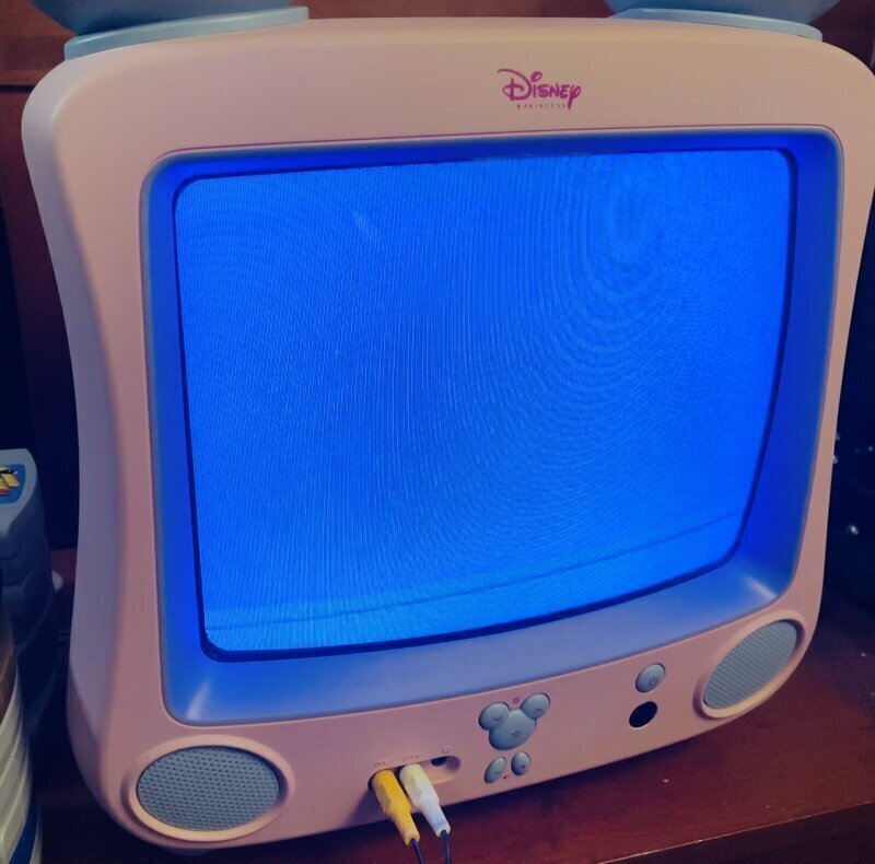
With this we find ourselves at the moment of truth. It's time to run our humble program on some actual hardware. We build the ROM file, transfer it over to the console, and…
We've produced some visually stunning graphics! If we want to visualize the previously-mentioned screen-scaling too, an easy test is to draw a square and observe its proportions.
// Again, use the RDP for drawing instead of this!

draw_square: // (a0 = minx, a1 = miny, a2 = dim, a3 = color)
  // dest = FRAMEBUFFER_ADDRESS +
  //   (((FRAMEBUFFER_WIDTH * miny) + minx) * BYTES_PER_PIXEL)

  la t0, FRAMEBUFFER_ADDRESS
  li t1, FRAMEBUFFER_WIDTH
  mul t1, t1, a1
  add t1, t1, a0
  li t2, BYTES_PER_PIXEL
  mul t1, t1, t2
  add t0, t0, t1

  li t3, 0 // y = 0

_draw_rectangle_loop_y:
  // if y >= dim, break
  bge t3, a2, _draw_rectangle_loop_y_done
  nop

  li t2, 0 // x = 0

_draw_rectangle_loop_x:
  // if x >= dim, break
  bge t2, a2, _draw_rectangle_loop_x_done
  nop

  // dest = dest_row + (x * BYTES_PER_PIXEL)
  li t6, BYTES_PER_PIXEL
  mul t6, t6, t2
  add t6, t6, t0

  // Store the pixel color at dest.
  sh a3, (t6)

  addi t2, t2, 1 // x++

  j _draw_rectangle_loop_x
  nop

_draw_rectangle_loop_x_done:
  // dest_row += stride
  addi t0, t0, FRAMEBUFFER_WIDTH * BYTES_PER_PIXEL

  addi t3, t3, 1 // y++

  j _draw_rectangle_loop_y
  nop

_draw_rectangle_loop_y_done:
  jr ra
  nop
This somewhat ugly but hopefully legible code is a direct translation of a pair
of nested c-style for loops that iterate over the rows and columns of
the square. This could be optimized quite a bit, but again this is just test
code that we don't have a reason to speed up yet. We want to call
draw_square between the screen clear and main loop. Again, we're just
drawing once at startup, not on every iteration of the loop.
// ...Elided screen clear...

li a0, 30 // minx value
li a1, 30 // miny value
li a2, 15 // dim value
li a3, 0xFF00FF00 // color (yellow)
jal draw_square
nop

// ...Elided main loop...
With this, we can observe that our square is drawn with equal width and height values. Additionally, halving the scale values doubles the square's respective dimensions, and vice versa. This implies that despite our imperfect understanding, we at least appear to be supplying the correct values.
And with that, we have in fact accomplished the goal we set at the beginning: we've produced and executed a program on the Nintendo 64.
Of course, we haven't quite fulfilled the promise of the title at the top of this page. Can we convince our Nintendo 64 to say hello?
Next Time: The Reality Coprocessor
This feels like a fine cliffhanger on which to pause. So where do we want to go from here?
A reasonable next step is to load up and display a minimal bitmap font. While that would be functional, it ignores the emotional core behind our decision to work with the Nintendo 64 in the first place: heart-felt appreciation of bad 3D graphics.
Thus we must lift the veil upon the Nintendo 64's Reality Coprocessor. The RCP, which we touched briefly when configuring the Video Interface, actually comprises two distinct processors: the Reality Signal Processor (RSP) and the Reality Display Processor (RDP). These chips are intended to do a lot of the computational heavy lifting across a variety of specialized tasks. They're pretty important for any sort of real 3D development on the N64.
We haven't exactly reached the fun part of this project yet (3D), let alone achieved the baseline level of interactivity to call this a game. Despite this, I'm pretty satisfied with our nascent efforts to talk to an old piece of hardware, which I think I now understand a little better.
We'll see when I feel like picking this up at some unspecified future point in time. Maybe I'll even write about it.
My initial plan was to write this project in C, which seems to have been the more popular choice for N64 developers back in the day. In the end, the proprietary nature of the official SDK spoiled my motivation to accurately relive the development practices of the past. Open source replacements have been developed in recent years, but leaning too heavily on modern libraries (that we didn't write ourselves) felt like a cop out. Plus, I write a lot of programs in C. I can't help but feel choosing C would have undercut the challenge a little too much (or worse, shifted the challenge over to toolchain management).
This
excludes my hacked together Emacs major-mode for N64 MIPS assembly with bass
assembler syntax. Sure do wish the built-in asm-mode worked like any other
mode in Emacs. Speaking of, additional tools of note that I'm using include the
text editor Emacs and the hex editor 010 Editor. These choices are entirely
personal and mostly inconsequential to any specific work we do here. Always use
whatever feels comfy.
It's clear I'm not a true assembly programmer just from the whitespace after operand commas. I do not care about this. The syntax bass offers is refreshingly readable - no superfluous sigils or punctuation, lax whitespace requirements. I think that's worth embracing. Well. I say that, but there are a few issues. The bass parser as of version 18 doesn't actually tokenize the input stream, it uses pretty basic string matching for handling the preprocessor. This surfaces in some frustrating ways, such as the whitespace handling around anonymous labels. Adding a space between a comma and label operand in, say, a branch instruction breaks bass's current string matching procedures. This is also why macro definitions can't move their opening curly brace to a new line. I came very close to writing a simple MIPS assembler from scratch just to kludge in a real lexer/parser.